Reverse-engineering an OBi302 ATA
Lately, I have been tinkering with IP phones and PBXes like Asterisk. I have found Polycom (now HP and formerly Plantronics/Poly) VVX phones to work well so when I saw a used Polycom analog telephone adapter (ATA) for cheap, I picked it up in order to potentially interface with analog phones as well. The unit I picked up has 2 analog telephone ports as well as two Ethernet ports. This OBi302 was originally designed by a company called Obihai Technology which made ATAs to interface with Google Voice. However, according to online documentation, they can be configured to interface with standard PBXex via SIP, etc.
I powered the device up, LEDs started blinking, however, I was unable to log
into the web interface on either the WAN port or the LAN port which features a
NAT for some reason: the default credentials I had found online did not work.
The situation didn't change after performing a factory reset. I did capture the
network traffic on the WAN network interface and saw DNS queries for domains
like root.pnn.obihai.com, ntp.telio.no and
initial.obihai.prov.telio.no. While the former didn't seem
particularly suspicious, the latter two indicate that this device had been
customized for the Norwegian IP telco Telio. It seemed plausible that they
provisioned the ATA with custom credentials as well. I had read in the ATA's
documentation that it can also be configured via the phone ports, however, I
could not get this to work either (foreshadowing).
UART console
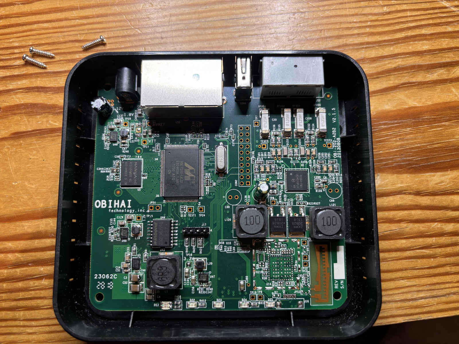
Opening up the device revealed no huge suprises: the main SoC Marvell 88E7200-LKJ2 combines ARM9 CPU and Ethernet switch and is connected to 64 MiB of DDR2 SDRAM and 16 MiB of serial NOR flash memory. The analog phone ports are implemented using the Skyworks Si32260 IC. The remainder is basically power regulation. There is also an unpopulated radio, perhaps DECT? The first step was now to find a serial console interface. The unpopulated J17 pinheader is a likely candidate which proved to be correct; pinout: 1-TX 2-RX 3-3V3 4-GND.
Unfortunately, the UART console didn't get me anywhere. All I could see was
Uncompressing Linux...<SNIP>... done, booting the kernel.

OBi202 login:
Actually, later on, I could I did not get the login prompt anymore so it must be shown conditionally. I could not break into the bootloader. Neither did simple root passwords work. This left me no option but desolder the flash chip and read it out in the hopes of finding the credentials. They must be stored somwhere on the device. However, it's not certain that I would be able to read them out if they happen to be encrypted by a hardware cryptographic key.
Reading out the flash ROM
I used flashrom together with a generic FT232H breakout board
connected via jumper wires to a ZIF socket for the flash chip after having
desoldered it. I struggled a lot to read out the device until I realized that I
needed to pull /HOLD and /WP highwhich resolved all initial issues. This is how
the W25Q128JV flash chip must be connected to the FT232H:
| FT232H | W25Q128JV |
|---|---|
| DBUS0 | CLK |
| DBUS1 | DI |
| DBUS2 | DO |
| DBUS3 | /CS |
| /HOLD → VCC | |
| /WP → VCC |
flashrom then gets invoked like so:
flashrom -p ft2232_spi:type=232H --{read,write} flash.binThe first thing I typically do when faced with an unknown flash blob is
running binwalk on it to hopefully discover partitions, etc. These
serial NOR flashes don't typically contain the partition table. Instead, the
bootloader typically supplies the partitions via device tree, kernel parameters,
etc. binwalk finds the following:
| Offset | Description |
|---|---|
| 0x50000 | uImage firmware image, header size: 64 bytes, data size: 2505264 bytes, compression: none, CPU: ARM, OS: Linux, image type: OS Kernel Image, load address: 0x8000, entry point: 0x8000, creation time: 2017-01-24 22:52:32, image name: "Linux-2.6.30.10" |
| 0x2D0000 | uImage firmware image, header size: 64 bytes, data size: 1229540 bytes, compression: none, CPU: ARM, OS: Linux, image type: OS Kernel Image, load address: 0x8000, entry point: 0x8000, creation time: 2011-10-12 21:50:39, image name: "Linux-2.6.30.10" |
| 0x480000 | SquashFS file system, little endian, version: 4.0, compression: gzip, inode count: 826, block size: 131072, image size: 5137593 bytes, created: 2018-06-14 19:29:57 |
| 0xB40000 | JFFS2 filesystem, little endian, nodes: 6, total size: 327692 bytes |
| 0xBA4410 | JFFS2 filesystem, little endian, nodes: 8, total size: 310268 bytes |
| 0xC00000 | SquashFS file system, little endian, version: 4.0, compression: gzip, inode count: 153, block size: 131072, image size: 1989074 bytes, created: 2018-06-30 01:59:34 |
| 0xE40000 | SquashFS file system, little endian, version: 4.0, compression: gzip, inode count: 437, block size: 131072, image size: 742658 bytes, created: 2017-01-09 19:31:48 |
| 0xF00000 | SquashFS file system, little endian, version: 4.0, compression: gzip, inode count: 13, block size: 131072, image size: 982209 bytes, created: 2016-05-04 22:18:43 |
That's a lot to unpack (ba dum tiss) but we can start to categorize a little: We have 2 ARM Linux kernel images, a few SquashFS file systems that are read-only and a couple of JFFS2 file systems that are likely used for storing persistent data (settings perhaps?).
Looking at the output of strings before 0x50000
reveals signs of a U-Boot bootloader and its environment:
bootargs=root=/dev/mtdblock5 rootfstype=squashfs mem=56M brd=$(boardID)
bootcmd=bootm 800000
bootdelay=0
baudrate=115200
ethaddr=08:00:3e:26:0a:5b
ipaddr=192.168.15.33
serverip=192.168.15.102
netmask=255.255.255.000
bootfile=bootrom.bin
boardID=DB
silent=1
What if we could set bootdelay to a positive integer and set
silent to 0? I tried the naive approach and modify the
binary and write it back to the flash chip. Unsurprisingly, this does not work:
the device shows no sign of life. There must be a checksum or even a
cryptographic signature somewhere.
After finding out that this family of SoCs ("Link Street") uses the Kirkwood
Boot Image format (thanks, Gemini) I could use the U-Boot mkimage
source code
to map the fields in the image header. Here are the highlights:
| Offset | Field | Value |
|---|---|---|
| 0x00 | Boot Type | 0x00 (DEF_ATTRIB) |
| 0x04 | Block Size | 0x00038e04 |
| 0x0c | Source Address | 0x00000140 |
| 0x10 | Dest. Address | 0x00100000 |
| 0x14 | Exec. Address | 0x00100000 |
So the U-Boot code starts at offset 0x140, is
0x38e04 long and gets loaded to 0x00100000 for
execution. This allowed me to extract this blob and load it into Ghidra with
base address 0x00100000. Curiously, this first thing the U-Boot
executable does is copy itself to 0x00380000 and jump to it. So in
order to get a sensible decompilation, the U-Boot blob needs to be loaded with
base address 0x00380000. This is, however, where I abandoned this
strategy. Instead, I wanted to focus on the other partitions and actually find
the factory defaults.
Finding the partition layout
Since I hadn't seen any traces of a device tree blob or kernel parameters
that resembled a partition layout in the U-Boot blob, I suspected that the
partition table might be hard-coded into the kernel. So I extracted the first
kernel image, stripped the U-Boot header and extracted the self-extracting
kernel image using a slightly modified version of
extract-vmlinux.
Then, I could run strings against the decompressed kernel and grep
for common partition labels like rootfs and kernel.
This yielded the following promising sequence of strings:
spi_flash0, u-boot, scratch,
rootfs, obi app, bluetooth. Looking where
these strings are referenced (offset by 0xc0008000) leads us to the
partition table (struct flash_platform_data and an array of
struct mtd_partition) which boils down to this partition table:
| Label | Offset | Size | Device |
|---|---|---|---|
| u-boot | 0x00000000 | 0x00050000 | mtd2 |
| kernel | 0x00050000 | 0x00280000 | mtd3 |
| scratch | 0x00b40000 | 0x000c0000 | mtd4 |
| rootfs | 0x00480000 | 0x006c0000 | mtd5 |
| flash0 | 0x00000000 | 0x01000000 | mtd6 |
| obi app | 0x00c00000 | 0x00240000 | mtd7 |
| bluetooth | 0x00f00000 | 0x00100000 | mtd8 |
Inspecting the partitions one by one did not yield the data I was looking
for. Neither did I find unit-specific data like certificates and keys. However,
I did find the mount points from the init script /etc/rc on the
rootfs partition:
| Device | Mount point |
|---|---|
| /dev/mtdblock4 | /scratch |
| /dev/mtdblock7 | /obi |
| /dev/mtdblock8 | /bluetooth |
The last thing the init script does is launching /obi/obi in the
background. The obi script launches obid in the
background which turns out to be a daemon that allows the main app to restart
itself, etc. Finally, the obi script launches
/obi/obiapp.
Decompiling obiapp
The executable obiapp on partition mtd7 appears to
run the show on the device. I spent way too much time wading through the
decompiled code in Ghidra, annotating along the way. What eventually led me down
the most fruitful road was searching for strings containing mtd.
This led me to 3 functions responsible for reading, erasing and writing
/dev/mtdchar6 which is just an abstraction for the entire flash
chip. Traversing the call tree backwards let me find various offsets in the
flash chip used for various data:
| Offset | Size | Purpose |
|---|---|---|
| 0x040000 | 0x0ff00 | unit data |
| 0x04ff00 | 0x00100 | u-boot build date |
| 0x400000 | 0x60000 | config data |
| 0x460000 | 0x10000 | factory default config data |
| 0x470000 | 0x00400 | last firmware update pack header |
Decrypting unit & config data
Parts of the unit data and the config data are RC4-encrypted. However,
investigating the decompilation reveals that the key is derived from known data.
The unit data key is comprised of the first 15 MD5 hash bytes of the unit data
header concatenated with the string thisisthesecretofobihaimfd 🙄 I
believe doing this kind of stuff makes it actually more likely for people to
reverse-engineer key derivation scheme since a string like that immediately
catches the eye when running strings on the executable. The unit
data contains the following data:
- Hardware version
- OEM part number
- Serial number
- RSA private key (1024 bit)
- Certificate (15-year validity, issued by C=US, ST=California, O=Obihai Technology Inc., OU=Obihai Trust Network, CN=Obihai Certification Authority, emailAddress=support@obihai.com)
- OBi number
- MAC address
- Part number
The config data key is composed of the config block's header combined with the unit's masked MAC address. The factory defaults block reveals the following strings among other things:
Teliontp.telio.noadminpassworduserpasswordIF ( $FWV < 3.0.0.3565 ) FWU http://firmware.telio.no/obihai/OBi202-3-0-0-3565.fwhttps://initial.obihai.prov.telio.no/initial/obihai/$DSN/$MAC/$DM/$FWV/; IF ( $TPRM0 == 1 ) EXIT; WAIT 120; GOTO retry;
So there we have it: the Telio domains and the admin password is
adminpassword. And it works. I now feel dumb not trying that one
before reverse-engineering this whole thing. Oh well...
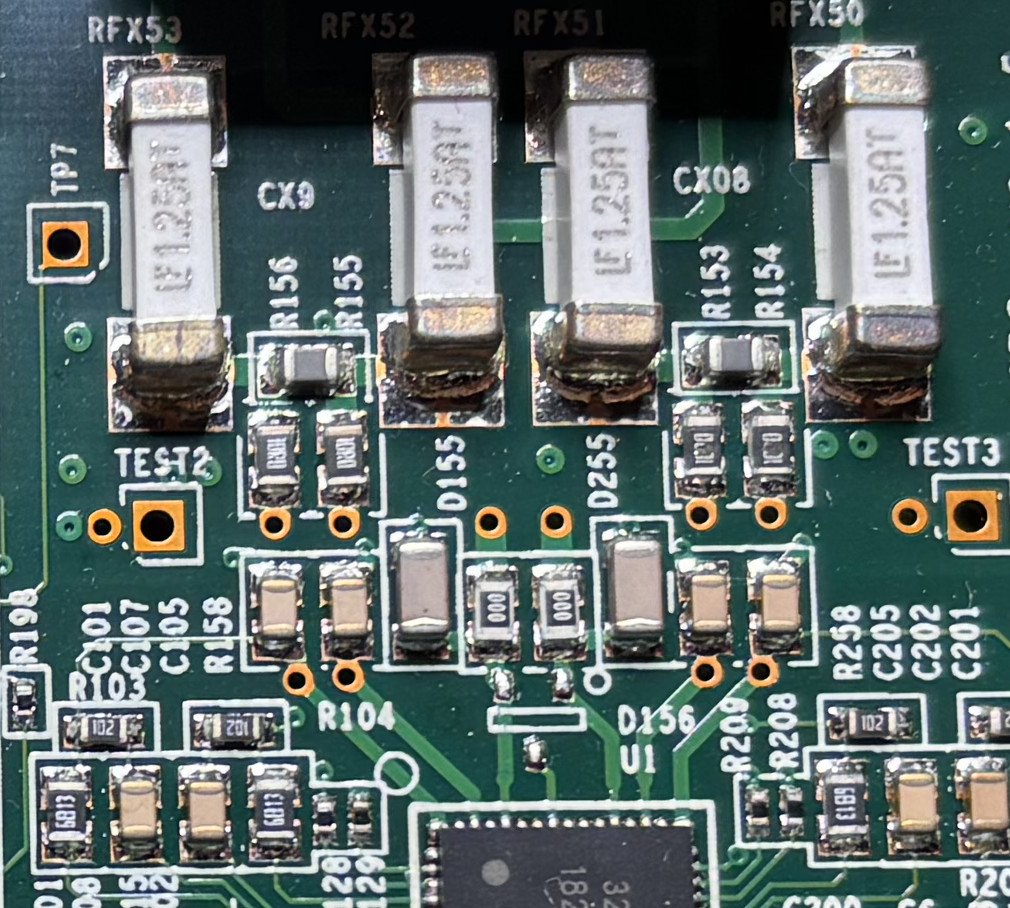
When I was finally able to configure the ATA, I found that the analog phone front-end chip was likely broken on my unit. At least, I couldn't get it to work and the series resistors on the phone lines were burned out -- bummer! At least the journey was fun and educational.
Appendix
The scripts to extract and decrypt unit and config data are available here: